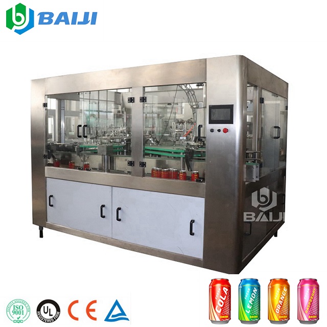
The cans enter the can filling machine through the can enter star wheel , reach the predetermined center of the filling equipment tank table, and then the filling valve descends along the supporting cam to center the can and pre-press and seal the can. The sealing pressure is in addition to the weight of the centering cover itself. In addition, it is generated by the pressure of a cylinder. The air pressure in the cylinder can be adjusted by the pressure reducing valve on the air control cabinet. The pressure is 0-40KPa (0-0.04MPa). The pressure depends on the material of the tank. When opening the vacuum At the same time as the channel, the back pressure gas in the filling cylinder rushes into the tank and flows into the vacuum channel. Vacuuming is used to implement the CO2 flushing process to remove the air in the tank. Through this process, the oxygen increase in the material during the filling process is minimized, and no negative pressure is generated in the tank, so even if the wall is very thin The aluminum cans can also be washed with CO2.

Regarding filling without vacuuming, the filling machine can directly apply CO2 gas from the original vacuum channel to directly flush the tank. After the vacuum valve is closed, equal pressure is established between the tank and the tank, the liquid valve is opened by the spring, and the filling begins. After three inlet tanks, the material flows down the tank wall, and the gas in the tank passes through the gas valve to the filling. Install the cylinder. After changing the length of the return air pipe, the height of the filling liquid level is changed. When the material level reaches the return gas pipe, the return gas is blocked, the filling is stopped, and an overpressure occurs in the upper gas part of the tank, so as to avoid the continuous flow of the material. Pull the fork to close the air valve and the liquid valve. After the exhaust valve, the exhaust gas makes the pressure in the tank equal to the atmospheric pressure, and the exhaust channel is far away from the liquid surface to avoid liquid being carried out during exhaust. During the exhaust period, the gas at the top of the tank shrinks, the material in the gas return pipe falls back into the tank, and the gas return pipe is emptied. At the moment when the can is out, the centering cover is lifted under the action of the cam, and under the action of the inner and outer guard plates, the can is separated from the can table, enters the can conveyor chain of the capping machine, and is sent to the capping machine. If the liquid level in the cylinder does not fluctuate, the lack of filling volume or foaming will occur during filling. Therefore, it is very important to control the liquid level in the cylinder fluctuatingly for normal filling. The entire liquid level control installation consists of a reed tube float liquid level sensor, a digital regulator, and a fair rotary valve (including valve positioner). The liquid level in the cylinder is measured by the reed tube float liquid level sensor 1, and converted into a 4-20mA current signal, through the mercury rotary joint 2. Passed to the digital conditioner 3, after PID adjustment, the input signal is sent to the electric valve positioner of the main liquid inlet valve 4 to control the opening of the main liquid inlet valve to achieve the purpose of controlling the liquid level of the filling cylinder. The liquid level in the filling tank can be set at any time on the digital conditioner according to requirements. The entire liquid level control installation will adjust the liquid level in the tank in real time according to the change of the set value.